Installing a Load Cell: Best Practices
Best Practice Installation
Each load cell installation is unique. Consult a structural engineer when your application requires very high accuracy, long-term stability, custom specifications, or when using in a varied R&D environment. In order to gain precise weighing results, be sure to use specified load applications for load cells. Load cells have a specified load direction; do not apply side forces, bending or torsional movements on load cells. Inappropriate loading applications will risk reducing the life of load cells, plus distortion of correct measurement results.


Using a rigid design for the support structure of load cells in compressive loading applications is preferred to pliable designs to achieve even lowering of all supports that also distributes tension, and provides an even contact surface.
Mounting the load cells to the support structure and rigid base plate, ensures even load transfer from the base of the load cell to the support structure. This structure must also have the capacity to support the forces corresponding with the load. Mounting aids may be needed for compliance with load cell installation. Seek assistance from the design engineer to determine the weighting of individual disturbance possibilities. Special considerations for weighing tanks, thermal expansions, monitoring levels, and horizontal movements for certain tank shapes and support structures are required to avoid measurement distortions. Your load cell support structure may need end-stops to limit lateral deflection, and elastomeric bearings can also regulate heat between the tank and load cell. Also if your load cell requires self-centering, the design engineer may suggest a pendulum load cell that will automatically guide the super structure into its original position.
Specific Applications
Gas Turbine Engine/Rocket: High accuracy measurements of the volumetric flow of gas through the pipeline. The turbine rotor turns the rotor blades by gas flow into the meter, measuring gas velocity. The rotor blades pass a pickup coil, generating an electrical signal pulse. The pulse is equal to a specific volume of gas. Total volumetric flow is recorded by the number of pulses. Expression of flow rate is measured in actual cubic feet or actual cubic meters, (ACF/AM3).
Engine Thrust Measurement: This built-to-order combination torque and thrust reactionary and rotary load cell product is constructed in all stainless steel for long term reliability. Applications in industrial environments include safe overload of 150% of capacity, ultimate overload at 300% of capacity. Call engineering for specifics.
Bin Weighing: To simplify load cell installations, use tank and bin weighing systems with capacities of up to 2500 pounds. Systems provide shock absorption for industrial installations and helps to prevent improper mounting, which can cause load cell damage. Make a complete four point system with 4000 pound maximum capacity with heavy duty shear beam type load cells and tank and bin weighing system.
Process Control Systems: The wide range of process controllers include temperature controllers, ramp and soak controllers, dual-zone controllers, and bench-top style process controllers. Microprocessor based controllers come with various displays, wire RTDs, process voltage and current. They can connect directly to the Ethernet network featuring an embedded web server, downloadable data acquisition software.
High Load Fatigue Testing: Reduces time needed for troubleshooting scale systems, analyzes conditions of strain gage-based load cells in scale and industrial applications. Test load cells without disconnection, easy-to-read, clear screen messages. Provides essential data, like possible distortions from overloads, metals fatigue or shock loading, and possible ground faults or bridge resistance electrical problems.
Bridge Testing: Using a terminal block system with bridging and testing accessories across different clamping technologies reduces inventory and logistics costs. A modular terminal block design can be combined with different terminal block types or individually for application flexibility.
Considerations before installation
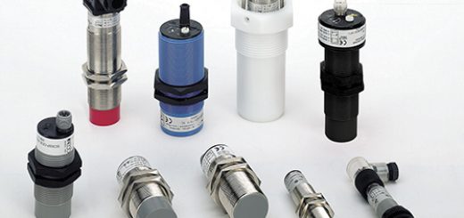
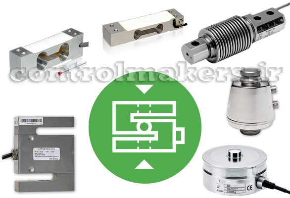
Types of Installations: In addition to typical installations of hydraulic, pneumatic, and strain gage types of load cells, OMEGA customers often ask about bending beam load cells, shear beams, canister type, ring and pancake load cells, and button and washer type load cell installations. Some other more advanced types of load cell installations for specific uses include helical, fiber optic, and piezo-resistive types of load cell installations. Contact Omega for details on your specific load cell installation requirements.
Load Orientation: Service technicians find the most common cause of accuracy problems with load measurements are incorrect load cell mounting which results in imprecise vertical loading that creates extraneous force errors. The loads must act precisely in the direction of the load cell.
Environment: Magnetic and electrical fields can sometimes create interference voltage within a measuring circuit. To ensure protection from EMC, place the load cell, connection cabling, and electronics in a shielded housing. Do not ground the indicator, amplifier, and transducer more than once.

Framework of Structure: Protect the measurement cable using steel conduits. Use shielded, low-capacity measurement cables such as HBM cables. Avoid stray fields from motors, contact switches, and transformers. Using a rigid design for the support structure of load cells in compressive loading applications, preferred to pliable designs, to achieve even/balanced lowering of all supports that also distribute tension, and providing an even contact surface. Mounting load cells to the support structure, and rigid base plate, ensures even load transfer from the base of the load cell to the support structure. This structure must also have the capacity to support the forces corresponding with the load.
Today’s mechanical scales can weigh loads of all kinds, from pharmaceuticals to tanks and shipping cars. Consistency of weight calculations and readings require the best weight balancing mechanism designs engineered to sense force, proper calibration, and maintenance. Depending on the output signals generated, we distinguish load cell designs according to weight detection, such as tension, compression, bending or shear, for example. Strain gage load cells convert on acting loads into electrical signals. The change in pressure of internal filling fluid measures weight using force balancing devices in hydraulic load cell designs. Higher accuracy requirements can be achieved using multiple dampener chambers which also operate on the force balance concept with pneumatic load cell engineering.
Using Load Cells to Weigh Trucks, Trains, and Aircraft
In the airline industry, weight is money. Every additional pound requires more fuel to lift, so making sure there’s enough gas in the tanks means knowing what the aircraft weighs. Weight distribution is another factor. Too much at the back and the aircraft flies nose-up, altering the angle of attack and consuming more fuel.

Weighing something as large as an aircraft—even a Boeing 747—is not particularly difficult. The way it’s done is with load cells. This White Paper from OMEGA Engineering explains how load cells are used to weigh very large objects. Sections address:
- The importance of weight in transportation
- Weighing technology
- Load cell basics
- Truck weighing systems
- Train weighing systems
- Aircraft weighing systems
The Importance of Weight in Transportation
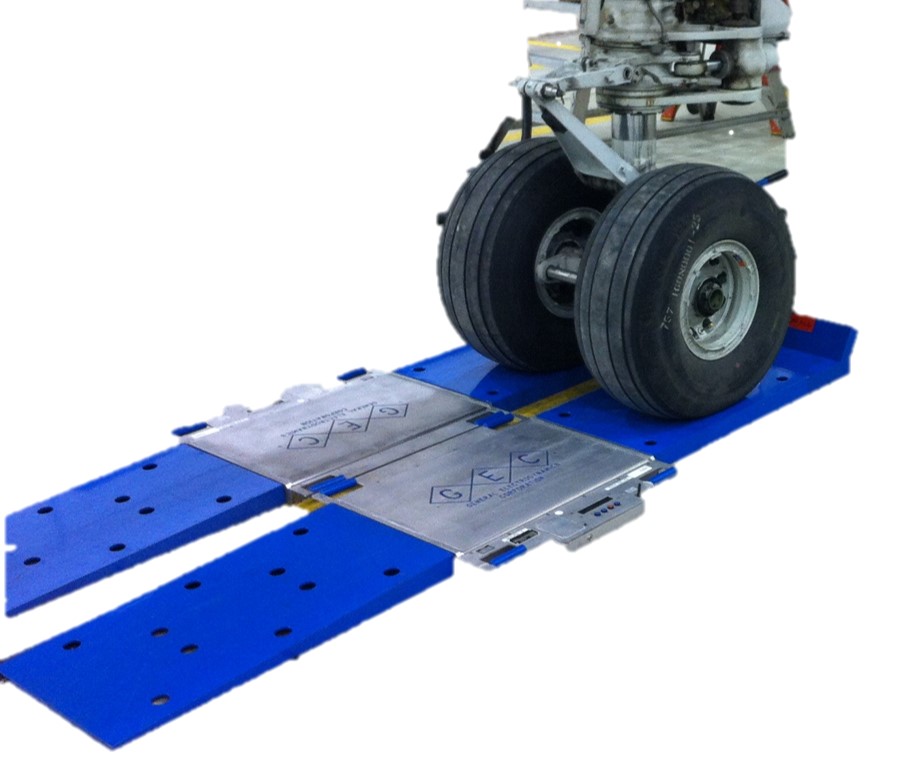
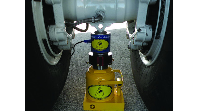
Load Cells to Weigh Aircraft
Aircraft, from two-seat civilian planes to the largest passenger and freight aircraft, are weighed regularly for two reasons. First, it’s an FAA requirement that the operator knows the weight of the aircraft, and as weight can change over time, periodic re-weighing is mandated. And second, a pilot may wish to know the weight of cargo or passengers and luggage taken on-board to determine both the fuel needed and the weight distribution (on small turboprop planes it’s not uncommon for passengers to be moved to even out weight distribution).
Truck weighing is another big application of load cells. Heavy vehicles cause significant damage to roadways and especially bridges, so states have limits on the maximum permissible load that may be carried. Enforcement of these limits is performed at roadside weigh stations where all trucks are required to stop for weighing.
Trains too need weighing. As with roads, excessive loads accelerate track wear, and as with aircraft, uneven weight distribution can result in stability issues. Freight moved by rail is sometimes priced on the basis of weight, making it essential to know the load in each rail car or wagon.
Weighing Technology
For centuries the primary means of weighing anything was with scales that used either the extension of a spring or a balance that compared one load with another. In recent decades though, for most industrial and commercial uses, these methods have been supplanted by load cells when a heavy weight needs to be measured.
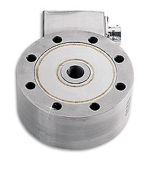
Load Cell Basics
A load cell is a device that converts a force (mass multiplied by gravity) to an electrical signal. This is commonly done through either the piezo-electric effect or with strain gauges. Piezo materials are those which output a small electric signal as they are compressed. While piezocrystals are the best known, there other similar materials that do the same, such as piezoceramics.

A strain gauge is an electrical device made from a material whose resistance changes with strain, usually manifested as deformation. These are used in load cells designed to deflect in response to a load. Most load cells are designed with a beam configuration that bends under load, although some use the expansion in cross-section resulting from longitudinal or axial compression. These generally give a less linear output than the bending configurations, making calibration a consideration.
A typical bending configuration is the ‘S’ beam load cell. In profile it looks like the letter ‘S’, and has four strain gauges fixed to the horizontal sections. When a load is applied vertically downwards on the top of the ‘S’ the bending puts two of gauges in compression and the other two in tension. Connecting these gauges in a Wheatstone Bridge arrangement enables the small changes in resistance to produce a measurable electrical signal.
For a strain gauge load cell to give useful measurements the load must be applied in the direction of operation. Side loads will result in inaccurate readings and may damage the device. Piezo sensor systems are more robust in this regard but are less accurate overall. In addition, the output from many piezo materials is quite temperature-dependent.
Load Cell Selection
- Measuring range
- Safe load limit (the maximum load that can be applied without causing a permanent shift in readings)
- Ultimate overload (the load that would break the load cell)
- Safe side load (the maximum lateral load the load cell can take without causing a permanent shift in readings)
Truck Weighing Systems
Most weigh stations use either piezo-based or strain gauge load cells. These are embedded into the road surface and the load created by each axle measured. A recent innovation is so-called Weigh-in-Motion (WIM) technology where the truck can be weighed accurately without needing to stop. These systems use a combination of load cells and inductive loops that detect vehicle presence. They are fast and accurate, and most importantly, eliminate the need for each truck to stop to be weighed. This overcomes the problems of traffic backups experienced at busy times, which often forces the temporary closure of the weigh station.
Train Weighing Systems
As with trucks, systems are available for both static and WIM measurement. These can determine individual axle loads, bogey loads and even the weight of an entire wagon or locomotive. Load cells are used in these systems and have accuracies of ±1% or better.