Calculate Size of Contactor, Fuse, C.B, Over Load Relay of DOL Starter
Calculate Size of Contactor, Fuse, C.B, O/L of DOL Starter
- Calculate Size of each Part of DOL starter for The System Voltage 415V ,5HP Three Phase House hold Application Induction Motor ,Code A, Motor efficiency 80%,Motor RPM 750 ,Power Factor 0.8 , Overload Relay of Starter is Put before Motor.
Basic Calculation of Motor Torque & Current:
- Motor Rated Torque (Full Load Torque) =5252xHP/RPM
- Motor Rated Torque (Full Load Torque) =5252×5/750=35 lb-ft.
- Motor Rated Torque (Full Load Torque) =9500xKW/RPM
- Motor Rated Torque (Full Load Torque) =9500x(5×0.746)/750 =47 Nm
- If Motor Capacity is less than 30 KW than Motor Starting Torque is 3xMotor Full Load Current or 2X Motor Full Load Current.
- Motor Starting Torque=3xMotor Full Load Current.
- Motor Starting Torque==3×47=142Nm.
- Motor Lock Rotor Current =1000xHPx figure from below Chart/1.732×415
|
Locked Rotor Current |
||
|
Code |
Min |
Max |
|
A |
1 |
3.14 |
|
B |
3.15 |
3.54 |
|
C |
3.55 |
3.99 |
|
D |
4 |
4.49 |
|
E |
4.5 |
4.99 |
|
F |
5 |
2.59 |
|
G |
2.6 |
6.29 |
|
H |
6.3 |
7.09 |
|
I |
7.1 |
7.99 |
|
K |
8 |
8.99 |
|
L |
9 |
9.99 |
|
M |
10 |
11.19 |
|
N |
11.2 |
12.49 |
|
P |
12.5 |
13.99 |
|
R |
14 |
15.99 |
|
S |
16 |
17.99 |
|
T |
18 |
19.99 |
|
U |
20 |
22.39 |
|
V |
22.4 |
|
- As per above chart Minimum Locked Rotor Current =1000x5x1/1.732×415=7 Amp
- Maximum Locked Rotor Current =1000x5x3.14/1.732×415=22 Amp.
- Motor Full Load Current (Line) =KWx1000/1.732×415
- Motor Full Load Current (Line) = (5×0.746)x1000/1.732×415=6 Amp.
- Motor Full Load Current (Phase)=Motor Full Load Current (Line)/1.732
- Motor Full Load Current (Phase)==6/1.732=4Amp
- Motor Starting Current =6 to 7xFull Load Current.
- Motor Starting Current (Line)=7×6=45 Amp
(1) Size of Fuse:
|
Fuse as per NEC 430-52 |
||
| Type of Motor | Time Delay Fuse | Non-Time Delay Fuse |
|
Single Phase |
300% |
175% |
|
3 Phase |
300% |
175% |
|
Synchronous |
300% |
175% |
|
Wound Rotor |
150% |
150% |
|
Direct Current |
150% |
150% |
- Maximum Size of Time Delay Fuse =300% x Full Load Line Current.
- Maximum Size of Time Delay Fuse =300%x6= 19 Amp.
- Maximum Size of Non Time Delay Fuse =1.75% x Full Load Line Current.
- Maximum Size of Non Time Delay Fuse=1.75%6=11 Amp.
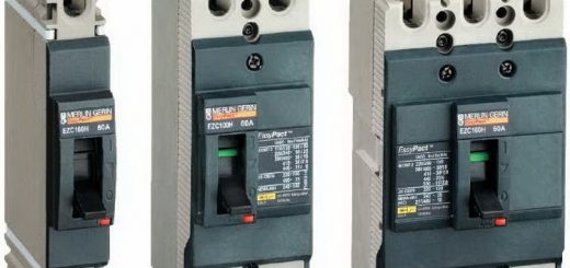
(2) Size of Circuit Breaker:
|
Circuit Breaker as per NEC 430-52 |
||
| Type of Motor | Instantaneous Trip | Inverse Time |
|
Single Phase |
800% |
250% |
|
3 Phase |
800% |
250% |
|
Synchronous |
800% |
250% |
|
Wound Rotor |
800% |
150% |
|
Direct Current |
200% |
150% |
- Maximum Size of Instantaneous Trip Circuit Breaker =800% x Full Load Line Current.
- Maximum Size of Instantaneous Trip Circuit Breaker =800%x6= 52 Amp.
- Maximum Size of Inverse Trip Circuit Breaker =250% x Full Load Line Current.
- Maximum Size of Inverse Trip Circuit Breaker =250%x6= 16 Amp.
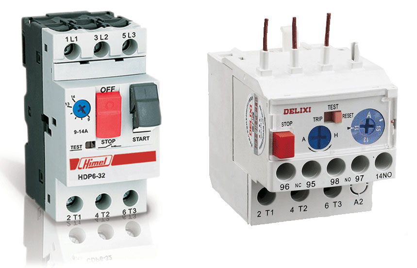
(3) Thermal over Load Relay:
- Thermal over Load Relay (Phase):
- Min Thermal Over Load Relay setting =70%xFull Load Current(Phase)
- Min Thermal Over Load Relay setting =70%x4= 3 Amp
- Max Thermal Over Load Relay setting =120%xFull Load Current(Phase)
- Max Thermal Over Load Relay setting =120%x4= 4 Amp
- Thermal over Load Relay (Phase):
- Thermal over Load Relay setting =100%xFull Load Current (Line).
- Thermal over Load Relay setting =100%x6= 6 Amp
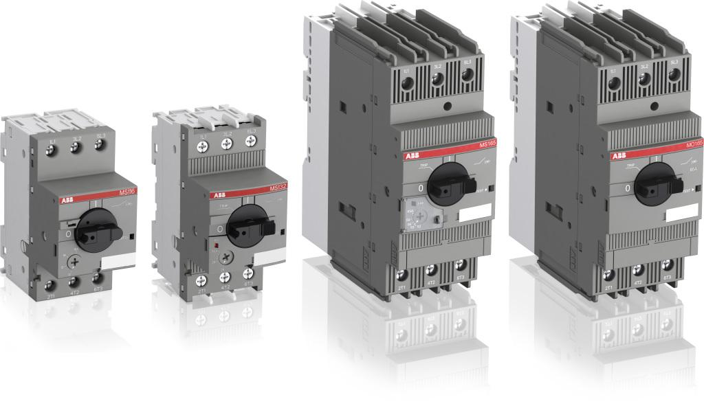
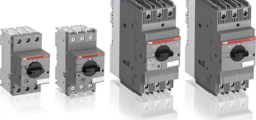
(4) Size and Type of Contactor:
|
Application |
Contactor |
Making Cap |
| Non-Inductive or Slightly Inductive ,Resistive Load |
AC1 |
1.5 |
| Slip Ring Motor |
AC2 |
4 |
| Squirrel Cage Motor |
AC3 |
10 |
| Rapid Start / Stop |
AC4 |
12 |
| Switching of Electrical Discharge Lamp |
AC5a |
3 |
| Switching of Electrical Incandescent Lamp |
AC5b |
1.5 |
| Switching of Transformer |
AC6a |
12 |
| Switching of Capacitor Bank |
AC6b |
12 |
| Slightly Inductive Load in Household or same type load |
AC7a |
1.5 |
| Motor Load in Household Application |
AC7b |
8 |
| Hermetic refrigerant Compressor Motor with Manual O/L Reset |
AC8a |
6 |
| Hermetic refrigerant Compressor Motor with Auto O/L Reset |
AC8b |
6 |
| Control of Restive & Solid State Load with opto coupler Isolation |
AC12 |
6 |
| Control of Restive Load and Solid State with T/C Isolation |
AC13 |
10 |
| Control of Small Electro Magnetic Load ( <72VA) |
AC14 |
6 |
| Control of Small Electro Magnetic Load ( >72VA) |
AC15 |
10 |
- As per above Chart
- Type of Contactor= AC7b
- Size of Main Contactor = 100%X Full Load Current (Line).
- Size of Main Contactor =100%x6 = 6 Amp.
- Making/Breaking Capacity of Contactor= Value above Chart x Full Load Current (Line).
- Making/Breaking Capacity of Contactor=8×6= 52 Amp.


In induction motor I will use AC7b ?
Hi Fadi . Yes AC7b the best choice for motor loads.
hi can you tell me what size contactor timmer and contactor coil should i use if i want to do star delta wiring for 100kw 415volt motor please
Hi , You can use
200A MCCB
125A Contactor with 220VAC Coil
0-16s Timer ( Its depend on your use )