Five factors that can affect your weighing system’s accuracy
You can ensure that your weighing system performs accurately by choosing components suited to your application and taking steps to control environmental and other forces acting on the system. This article discusses five factors that can affect the weighing system’s accuracy and provides advice on selecting, installing, and operating the system to handle these factors.
Weighing to measure dry bulk material quantities and flowrates has several benefits: Unlike volumetric measurement, weighing can measure a material quantity without correction factors for the material’s bulk density. Weighing doesn’t require contact with the material, making it suitable for measuring corrosive materials and operating in corrosive environments. It’s also a widely accepted means of quantifying packaged products for sale.
A weighing system can take any of several forms but typically includes one or more load cells that support (or suspend) a weigh vessel or platform, a junction box, and a weight controller. When a load is applied to the weigh vessel or platform, a portion of the load is transmitted to each load cell. Each cell sends an electrical signal proportional to the load it senses via a cable to the junction box. The load cell signals are summed in the junction box and sent via one larger cable to a weight controller, which converts the summed signal to a weight reading. This weight reading’s accuracy can be affected by the system components’ quality and the system’s installation and operation in your environment.
To help you choose high-quality weighing system components, take advantage of the expertise of weighing equipment suppliers. An important part of this selection process is determining how the system will be installed and what factors can affect its operation once it’s up and running in your process line. Consider how these five factors can affect your system’s weighing accuracy:
- Load cell accuracy.
- Load factors.
- Environmental forces.
- Interference with signal transmission.
- Instrumentation and control.
1. Load cell accuracy
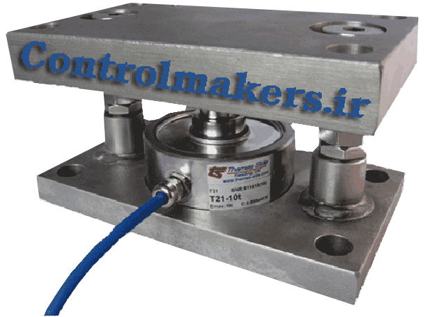
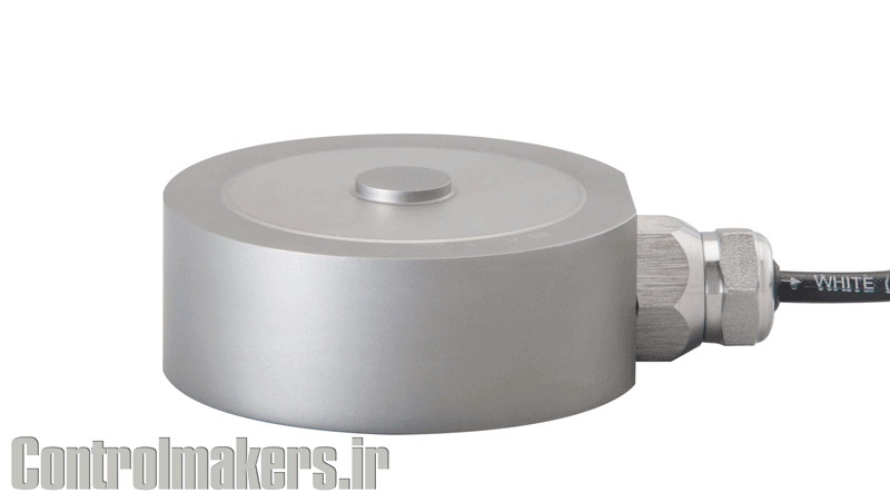
Selecting a top-quality load cell for your weighing system is the first step in obtaining weighing accuracy. The load cell (also called a load sensoror transducer) is a piece of machined metal that bends with the load’s mechanical force and converts the mechanical force into an electrical signal. The bend doesn’t exceed the metal’s elasticity and is measured by strain gauges bonded at points on the cell. As long as the load is applied to the proper spot on the load cell, the strain gauges provide a proportional electrical signal.
The key specifications for a load cell that will provide accurate weight information are:
- Nonlinearity: ±0.018 percent of the load cell’s rated output.
- Hysteresis: ±0.025 percent of the load cell’s rated output.
- Nonrepeatability: ±0.01 percent of the load cell’s rated output.
- Creep: ±0.01 percent of the load cell’s rated output in 5 minutes.
- Temperature effect on output: ±0.0008 percent of the load per degree Fahrenheit.
- Temperature effect on zero: ±0.001 percent of the load cell’s rated output per degree Fahrenheit.
Understanding the specifications.
Although every specification won’t necessarily apply to your weighing system installation, it’s important to understand each specification to determine the load cell’s combined accuracy.
Nonlinearity is the load cell calibration curve’s maximum deviation from a straight line, starting at zero load and ending at the cell’s maximum rated capacity. Nonlinearity measures the cell’s weighing error over its entire operating range. The worst-case nonlinearity specification of ±0.018 percent is seen over the load cell’s full range. The smaller the change in weight on your load cell, the smaller the error resulting from nonlinearity.
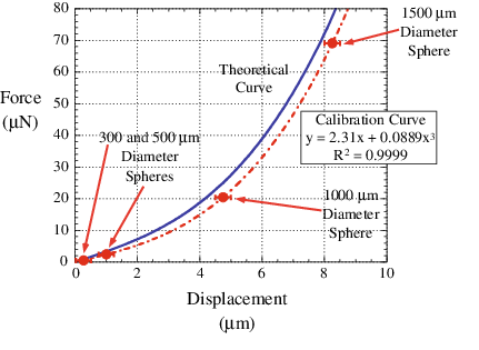
Figure 1: Typical Load Cell Calibration Curve
Hysteresis :
Hysteresis is the difference between two load cell output readings for the same applied load — one reading obtained by increasing the load from zero, the other by decreasing the load from the load cell’s maximum rated capacity. As with nonlinearity, the worst-case ±0.025 percent hysteresis specification is seen over the load cell’s full range, and the error caused by hysteresis diminishes with small weight changes.
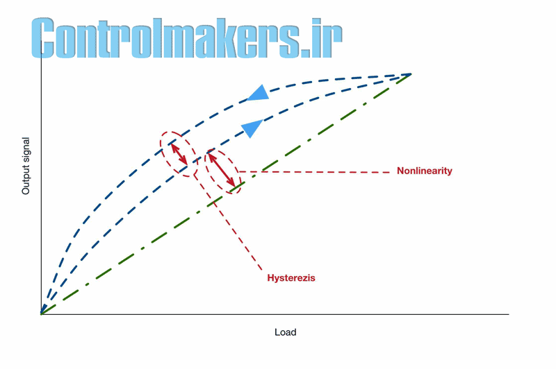
In an application such as batching, where you typically need accurate weight measurements only during filling, you can ignore the error caused by hysteresis. Hysteresis error normally falls into a different region on a load cell’s calibration curve than nonlinearity error, as shown in Figure 1. As a result, the specifications for these two errors are combined on some load cells into an algebraic sum, called a combined error specification, of ±0.03 percent.
Nonrepeatability :
Nonrepeatability is the maximum difference between load cell output readings for repeated loadings under identical loading conditions (that is, either increasing the load from zero or decreasing the load from the load cell’s maximum rated capacity) and environmental conditions. The nonrepeatability specification is ±0.01 percent over the load cell’s full range. Nonrepeatability can affect the weight measurement in any weighing application. You can determine the worst-case nonrepeatability specification by adding the nonrepeatability error to the load cell’s combined error.
Creep :
Creep is the change in load cell output over time when a load remains on the cell for a long time. In a 2- to 3-minute batch or filling cycle, creep isn’t a significant problem. But if you use load cells to monitor inventory in a storage silo, you need to consider creep effects.
Temperature changes :
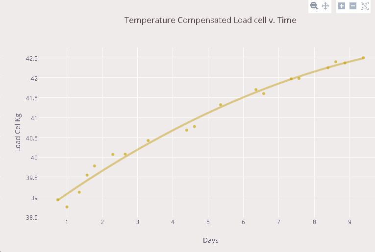
Temperature changes can cause weighing errors. Most load cells are temperature-compensated to reduce these errors. But if your weighing system is subject to large temperature changes during the weighing cycle — for example, if an outdoor weigh vessel is exposed to low overnight temperatures but heats up quickly in the daytime sun — consider how temperature can affect the load cell output. If the only significant change affecting your weighing system is between summer and winter temperatures, you can recalibrate the load cells once when the season changes to correct for any temperature-caused errors.
Temperature changes affect load cell output by changing the load cell’s sensitivity, and you must consider this effect unless you perform a new calibration for each large temperature change. The temperature effect on the load cell at zero load causes the cell’s entire output range to shift. But if the load cell rezeroes (that is, tares in the net-weight mode) before it starts the weighing cycle — such as in a batching application — you don’t need to be concerned about this temperature effect on zero load.
1. Considering your load cell’s response time .
The load cell’s response time is another factor to consider for some applications. The typical load cell behaves like a stiff spring that oscillates, so to achieve an accurate weight reading, the load cell must settle — that is, stop oscillating — in less time than the required weighing period. While load cell response time is typically not important for a batching application, a high-speed checkweighing or rotary filling machine requires fast-responding load cells. Such load cells dampen their own natural oscillating frequency when a load is applied to them. However, the load cells don’t reject vibrations applied to them from outside sources, such as nearby equipment, so you still need to isolate the load cells from such vibration sources
2. Load factors
Ensure that the load is applied to each load cell in your weighing system as specified by the manufacturer. An improperly applied load, such as a twisting load, causes the strain gauges in the cell to experience strain and send a signal change proportional to the twisting rather than the load’s weight.
For accurate weighing, the load cells alone must support all the weight to be measured. For example, rigid conduit connections and rigidly mounted piping on a weigh vessel will support some of the load and prevent the total load from being transmitted to the load cells. To avoid this problem, use flexible connections that won’t support part of the load. And if you use bumpers or check rods to keep the weigh vessel from swinging and swaying, make sure that they don’t support any of the load.
Correctly align each load point assembly — that is, each load cell and its mounting hardware — to ensure that the mounting hardware channels the load directly through the load cell. For example, for compression-mounting load cells under a hopper, align each load point assembly directly under the hopper leg to avoid pulling or pushing between assemblies on the other legs. Each load cell should be level, and all should be on the same plane to ensure that they share the load equally.
Make sure that the floor or structure under the load cells is strong enough to bear the weight of the vessel and its contents — as well as the weight of other equipment resting on the same floor or structure — without flexing. This will ensure that the load point assemblies remain level ±0.5 percent from zero to full load and prevent unwanted side loads on the load cells that can impair the weighing system’s accuracy.
If your weigh vessel has long spindly legs, the legs can spread apart as material is loaded into the vessel. This introduces side loads to the load cells and can cause system binding, which prevents the load cells from sensing the full load. You can add cross bracing to the legs to strengthen the structure and preserve your weighing accuracy.
3. Environmental forces
Ensure that only the weight force is transmitted to each load cell. Other forces, including environmental forces such as wind loading, shock loading, vibration, large temperature changes, and pressure differentials, can produce errors in the load cell signal.
Wind loading. Wind loading can affect an outdoor weighing system or a low-capacity indoor system. For example, outdoors, a 30-mph crosswind on a weigh vessel exerts forces on the load cells that have nothing to do with weight, causing the windward cells to sense a lighter load and the leeward cells to sense a heavier load. In such a case use higher-capacity load cells to prevent overloading the leeward cells. Indoors, an active overhead air conditioning vent can also create inaccurate small-increment (such as 1-ounce) measurements on a low-capacity weighing system, such as a small platform scale. You can use a Plexiglas cover over the platform scale to block or divert the stray air currents.
For accurate weighing, the load cells alone must support all the weight to be measured.
Shock loading.
Shock loading occurs when heavy material is dumped onto a weighing system, causing forces greater than the system’s rated capacity and damaging the system. You can use higher-capacity load cells that can handle this shock loading, but this will degrade the system’s resolution (the smallest increment that the system can weigh). Controlling the material flow onto the weighing system with a feeder, specially designed loading chute, or other device can prevent shock-loading damage.
Vibration.
Vibration from process equipment and other sources near the weighing system can cause the load cells to measure the weight of material as well as vibration that’s transmitted to them, which the cells sense as mechanical noise. You can reduce or prevent vibration effects by isolating the weighing system from vibration sources when possible or using weighing system instrumentation with algorithms that remove vibration effects.
Large temperature changes.
Whether your weigh vessel is indoors or outdoors, large temperature changes can cause it to expand or contract. This causes errors in the weight reading and can damage the load cells. If your weighing system is exposed to large temperature shifts, install load cells and mounting hardware that can handle the vessel’s expansion and contraction.
Pressure differentials.
A pressure differential can create weighing errors by applying unwanted forces to the weighing system. A pressure differential can occur, for example, when a weigh vessel is installed between a pressurized plant floor and another floor at ambient pressure. To minimize weighing errors, calibrate the load cells to the pressurized floor’s constant pressure level. If the pressurization isn’t constant, install the weigh vessel elsewhere.
A pressure differential can create weighing errors by applying unwanted forces to the weighing system.
Another form of pressure differential is created in an unvented weigh vessel: When material flows quickly into a closed weigh vessel, it displaces a volume of air equal to the material volume. If the air can’t escape from the vessel through a vent, the flexible connections that attach the material inlet and outlet piping to the weigh vessel will expand as the undisplaced air floods into it, and this expansion will apply side forces to the load cells, creating weighing errors. To prevent this problem, properly vent your weigh vessel.
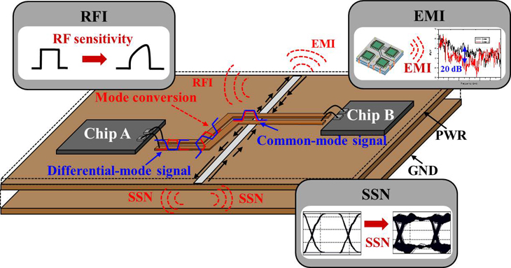
4. Interference with signal transmission
In addition to ensuring that the load cells measure only the desired weight, it’s equally important to ensure that the weight controller measures only the load cell electrical signal. Radio frequency interference (RFI), electromechanical interference (EMI), moisture, and temperature can all interfere with this electrical signal.
RFI and EMI.
Just as vibration is mechanical noise (that is, interference) to a load cell, RFI and EMI are electrical noise to the load cell signal sent from the cells to the weight controller. RFI and EMI sources include lightning, portable two-way radios, large power lines, static electricity, solenoids, and electromechanical relays.
One major step toward preventing these electric noise sources from affecting your weighing accuracy is to isolate the load cell low-voltage signal (typically equal to 1 millionth of a penlight battery’s output) in a shielded cable and then route the cable in a conduit separate from other cables. But be aware that the load cell cable shield can also be an open door for electrical noise. To prevent the noise from affecting your load cell function, properly ground the shield by tying it at only one end to a true ground, which will prevent the shield from forming a ground loop.
Moisture.
Moisture that enters the weighing system’s junction box can wick itself into the cables to each load cell and reduce the capacitance between signal lines. This causes the load cell excitation lines (the lines carrying electrical energy to the cells) to couple with the signal lines (the lines carrying the cells’ signals back to the junction box), creating electrical noise that can affect the weighing accuracy. To avoid this, use a waterproof NEMA 4-rated junction box and plug any unused junction box holes. If moisture is present in your environment, also use load cells that are hermetically sealed at both the strain gauge area and the cable entry. The strain gauge area should be welded shut. The cable entry, which is the most vulnerable to moisture because moisture can wick up through the cable, should have a welded fitting that includes a glass-to-metal hermetic header.
Temperature.
A load cell cable conduit that’s subject to large temperature changes or that runs more than 50 feet from the junction box to the weight controller can be affected by temperature fluctuations, which cause resistance changes in the cable. This can cause excitation changes, in turn causing load cell signal changes. To prevent these temperature problems, use six-wire load cell cable, which allows the weight controller to make ratiometric readings of the load cell signal that ignore excitation-change-induced changes.
5. Instrumentation and control
Following the advice in the previous four sections will ensure that your load cell signal arrives at the weight controller in the cleanest form possible. But chances are, the signal still won’t be absolutely clean. Why not? Remember that the load cell transmits a signal that represents mechanical force, and vibration is a mechanical force. Similarly, the weight controller measures an electrical signal, and RFI and EMI areelectrical signals. But even if you can’t entirely eliminate mechanical and electrical noise sources, you can select a weight controller that helps clean up less-than-perfect weight signals and improves weighing accuracy.
How a weight controller cleans up weight signals.
Let’s take a look at how a weight controller can clean up the weight signal from a load cell. Consider the example of a signal coming from a typical weigh hopper, as shown in Figure 2a. Theoretically, the weight signal should move smoothly upward on the Figure 2a plot as material enters the hopper. But in reality, the signal may roll slowly, caused by the hopper’s swinging and swaying or by material entering the hopper in pulses, such as from an improperly installed auger. Mechanical vibration, such as from a hopper agitator or nearby process equipment, or electrical noise, such as from large power lines nearby, can also cause fast jitter in the signal.
If the signal enters a weight controller equipped with an analog low-pass filter (typically rated from 5 to 20 hertz), the filter will strip off random jitter — thus providing analog averaging — and yield a signal similar to that in Figure 2b.
A weight controller equipped with a dual-slope, analog-to-digital converter can also help digitally average other random signal fluctuations. Once the controller digitizes the signal, it can average the readings to smooth out the slow rolling and yield a representative signal like that in Figure 2c. Such digital averaging is especially useful for averaging from 1 to 250 readings per weighing cycle when the weighing system is set up to take weight readings at single-unit increments (for example, at 1-pound increments rather than 5-pound increments on a system with a 200-pound range). In some applications, you may have to use a weight controller that also provides built-in proprietary algorithms that automatically eliminate the effects of signal fluctuations down to 0.25 hertz.
Weight controller requirements.
The weight controller requires several other features to ensure weight accuracy. The controller should have an analog-to-digital converter that can be synchronized with a 60-hertz line frequency to avoid the problem of “60-hertz hum” caused by noise from 60-hertz power lines and equipment. The controller’s internal components should provide proper analog signal shielding to isolate the signal from stray interference. The controller’s analog circuitry should also have high-grade electrical components to accurately process the load cells’ low-voltage weight signals.
Finally, consider three key weight controller specifications to ensure that your weighing system is accurate:
- Nonlinearity: ±0.01 percent of span (that is, the weighing system’s selected operating range).
- Temperature effect on zero: ±0.0027 percent of span per degree Fahrenheit.
- Temperature effect on output: ±0.0027 percent of span per degree Fahrenheit.
As with a load cell, nonlinearity effects on the weight controller are negligible for small weight changes. You can also ignore the temperature effect on zero if the controller tares before starting the weighing cycle. However, you do need to consider how temperature effects on output can affect your weighing accuracy.
What accuracy you can expect
Let’s compute the worst-case total weighing error for an example weighing system to see how the system’s components affect accuracy. We’ll consider the worst-case total error for only the load cells and weight controller in a gain-in-weight batching system.
This system weighs 400 pounds of material in a 100-pound weigh hopper, requiring the load cells to support a total of at least 500 pounds. The hopper is suspended from three load cells, each with a rated capacity of 200 pounds, yielding a total capacity of 600 pounds. A 20°F temperature change also occurs between seasonal system calibrations.
In a batching process, we’re concerned only with the weighing system components’ specifications for nonlinearity, nonrepeatability, and temperature effect on output, and nonlinearity error isn’t a concern because batching is a sequence of partial weighments.
As a result, the formula for computing the system’s worst-case total error is:
[(IT)2 + (LN)2 + (LT)2]1/2
where IT is the instrument’s (weight controller’s) temperature effect on output (0.000027 x 600 pounds x 20°F), LN is the load cell’s nonrepeatability (0.0001 x 600 pounds), and LT is the load cell’s temperature effect on output (0.000008 x 500 pounds x 20°F). In this example, the worst-case total error is 0.34 pounds. Remember that this is a worst-case number; a correctly installed weighing system will yield a lower error.
A final caution
Achieving this kind of weighing accuracy means considering many factors, both mechanical and operational, that can affect your weighing system. Choosing quality components especially suited to your application will go a long way toward ensuring that your system provides the accuracy you need. These components typically have impressive worst-case specifications, and their actual performance is usually better than the specification. As a general rule, select load cells and a weight controller with accuracies 10 times better than your desired system accuracy. And pay close attention to how you install and operate the system to prevent mechanical forces and electrical noise from reducing your weighing accuracy.
Read More :
Improve weighing system’s accuracy