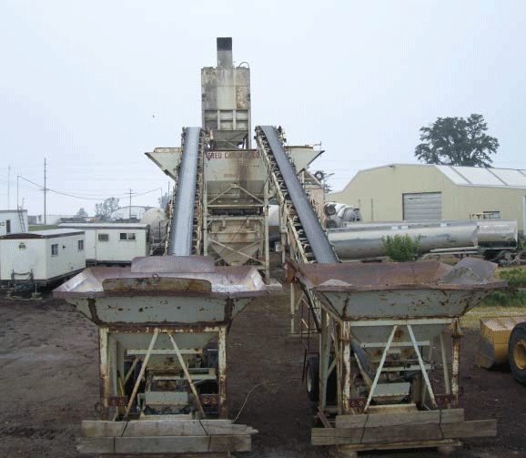
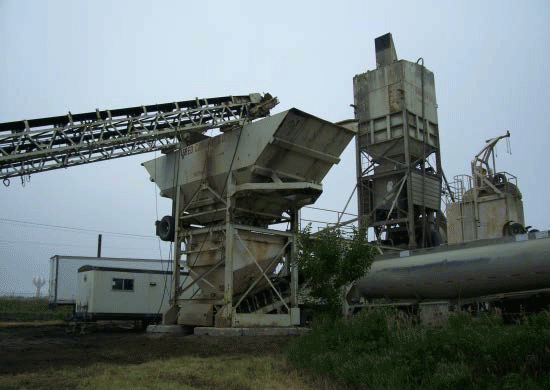
There are two main types of concrete batch plants: truck mix and central mix. Truck mix batch plants load out the ingredients of the concrete mixture into a mixer truck, and the truck mixes them to form the concrete. Central mix facilities mix the ingredients internally before being loaded into the truck.
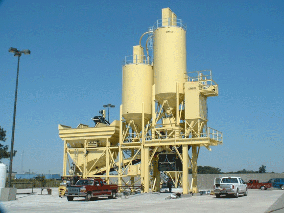
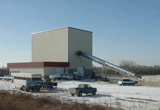
Each of these types of facilities can be either portable, or stationary. A portable facility will generally be built onto truck trailers to facilitate transportation on public roadways. The structure of a portable facility is almost always comprised of an open framework, and so building downwash is generally not applicable. At a stationary facility, the structure can be either a solid building or an open framework. In some cases one or more of the emission sources may be enclosed inside a building.
Regardless of the type of facility, the emission sources are generally consistent. This document lists the emission sources one would expect to see at a concrete batch plant, their descriptions, and the suggested method for modeling each one.
Fugitive Emissions
There are several sources of fugitive emissions at a concrete batch plant: the unloading of aggregate or sand from truck, rail or barge onto storage piles; the movement of aggregate and sand to maintain the shape of storage piles; the process of filling the bucket of the front-end loader for transfer to the hoppers; wind erosion of the sand and aggregate storage piles; and the movement of delivery trucks, cement trucks and front-end loaders over the haul roads and yard surfaces. The emissions generated by these activities are considered fugitive and are therefore generally not included in the modeling analysis.
Delivery to Storage Silo (Cement and Cement Supplement)
Unloading of cement or cement supplement into elevated storage silos from truck, rail or barge. Due to the sensitivity of cement and the cement supplement to moisture, this is always an enclosed system. The emissions that are generated by this process are generally passed through a baghouse located on top of the storage silo, or through a central baghouse. The DNR recommends the emissions from each silo be modeled as a point source using the stack characteristics of the baghouse that controls it.
Transfer to Aggregate Load-In Hopper (Aggregate and Sand)
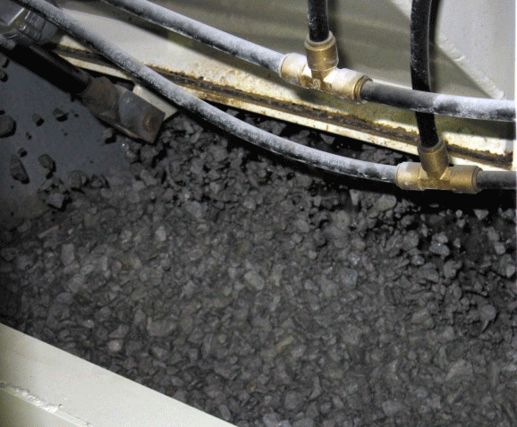
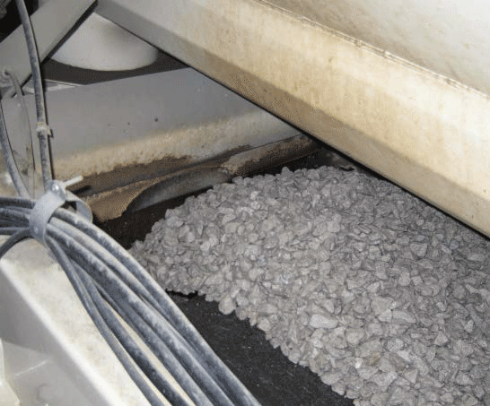
The aggregate and sand are generally transferred to a conveyor by using a front-end loader to move the material from the ground storage piles to a hopper that dumps onto the conveyor. The emissions are generated as the material falls from the bucket of the front-end loader into the hopper. In some cases, the piles may be placed on top of under-ground hoppers, which are fed by gravity instead of front-end loaders, or the front-end loader may dump the aggregate directly into the overhead bins. In either of these cases, this source is eliminated and does not need to be included in the analysis.
![]()
When a front-end loader is used to transfer the material to a hopper, the DNR recommends the emissions be modeled as a volume source located at the hopper. The release height is the midpoint between the top of the hopper and the bottom of the bucket of the front-end loader as it dumps the material into the hopper. The initial horizontal dimension (σy) is the square-root of the lateral area of the hopper divided by 4.3. The initial vertical dimension (σz) is the distance the material falls from the bucket of the front-end loader to the top of the hopper divided by 2.15.
If the exact dimensions of the hopper are not available, the hoppers are generally about 12 feet by 12 feet, and about 10 feet tall. The bottom of the bucket of the front-end loader can be assumed to be 3 feet above the top of the hopper when dumping material. There may be more than one hopper, and the hoppers may be used for different materials (e.g. sand vs. aggregate). Therefore, the emission rate may not be the same for each hopper. If only one hopper will be able to be filled at a time, then the DNR recommends that the hopper being filled with aggregate be modeled.
This source can be assumed to operate for 12 minutes (per front-end loader) out of each hour for both types of concrete batch facilities. Therefore the modeled hourly emission rate can be reduced by a factor of 12x/60, where x is the number of front-end loaders used to feed the hopper(s).
Transfer to Elevated Storage Bins (Aggregate and Sand)
Emissions are generated as the aggregate and sand fall from the conveyor, or bucket of the front-end loader, into the elevated storage bins. It is sometimes possible to partially enclose this source to reduce the amount of emissions that are generated. In this case a partial emission reduction may be applied.
![]()
These emissions may be modeled as a volume source, or series of volume sources, located at the bins. The release height is the midpoint between the top of the bins and the top of the conveyor. If the length of the bins divided by their width is less than 1.5, then the DNR recommends the bins be represented using a single volume source whose σy is the square-root of the lateral area of the bins divided by 4.3. If the length of the bins divided by their width is greater than or equal to 1.5, then the DNR recommends the bins be represented using a series of volume sources whose σy is the square-root of the lateral area of the bins divided by 2.15. The σz is the distance the material falls from the top of the conveyor (or the bottom of the bucket of the front-end loader) to the top of the bin divided by 2.15.
The dimensions of the elevated storage bins vary widely based on the capacity of the facility. However, if the exact dimensions of the bins are not available, a conservative estimate of 10 feet by 10 feet (per bin), and about 15 feet tall can be used. The top of the conveyor (or the bottom of the front-end loader) can be assumed to be 3 feet above the top of the bins.
Unless there are multiple conveyors or front-end loaders feeding the bins or multiple front-end loaders feeding the conveyors, it can be assumed that only one type of material is being loaded into the bins at a time. The DNR recommends the weighted average emission rate from filling the bins with aggregate and sand be used. Alternatively, a conservative estimate can be determined by using the emission rate for filling the bins with aggregate only.
This source can be assumed to operate for 30 minutes out of each hour for both types of concrete batch facilities. Therefore the modeled hourly emission rate can be reduced by a factor of 30/60.
Aggregate Weigh Hopper (Aggregate and Sand)
Gates on the bottom of the elevated storage bins open and allow the aggregate and sand to fall into the aggregate weigh hopper, creating emissions in the space between the bottom of the elevated storage bins and the aggregate weigh hopper. Emissions are also generated as the material falls from the bottom of the aggregate weigh hopper onto the conveyor that feeds the truck loadout or central mixer. Note that it is impossible for emissions to be generated from both the filling and emptying of the weigh hopper simultaneously.
These emissions should be modeled as a volume source or series of volume sources, located at the aggregate weigh hopper. The release height is the midpoint between the bottom of the elevated storage bins and the top of the conveyor that feeds the truck loadout or central mixer. If the length of the aggregate weigh hopper divided by its width is less than 1.5, then the DNR recommends the source be represented using a single volume source whose σy is the square-root of the lateral area of the aggregate weigh hopper divided by 4.3. If the length of the aggregate weigh hopper divided by its width is greater than or equal to 1.5, then the DNR recommends the source be represented using a series of volume sources whose σy is the square-root of the lateral area of the aggregate weigh hopper divided by 2.15. The σz is the distance between the bottom of the aggregate bins and the top of the conveyor that feeds the truck loadout or central mixer divided by 2.15.
This source is eliminated at some facilities by weighing the material in the elevated storage bins directly and then drawing off until the weight of the material remaining in the bins equals the original weight minus the weight of the material required for the batch. In these cases, the DNR recommends the emissions from the unloading of the elevated storage bins onto the conveyor that feeds the truck loadout or central mixer be added to the sources that represent the elevated storage bins.
This source can be assumed to operate for 42.5 minutes out of each hour for truck-mix facilities, and for only 30 minutes out of the hour for central-mix facilities. Therefore the modeled hourly emission rate can be reduced by a factor of 42.5/60 and 30/60 for truck-mix and central-mix facilities respectively.
Cement Weigh Hopper Loading (Cement and Cement Supplement)
Emissions are generated by the filling of the cement weigh hopper from the cement and supplement silos. The exhaust from this source is usually vented through a cartridge filter in the side of the weigh hopper, or through a central baghouse. The DNR recommends this source be modeled as a point source using the stack characteristics of the vent or baghouse stack.
This source can be assumed to operate for 37.5 minutes out of each hour for truck-mix facilities, and for only 30 minutes out of the hour for central-mix facilities. Therefore the modeled hourly emission rate can be reduced by a factor of 37.5/60 and 30/60 for truck-mix and central-mix facilities respectively.
Truck Mix Loadout
Emissions are generated as the cement, supplement, sand and aggregate are transferred to the cement truck. Truck loadouts range from being completely uncontrolled, to having a boot, skirt or hood that surrounds the opening at the top of the truck, to being aspirated into a baghouse and completely surrounded by a building.
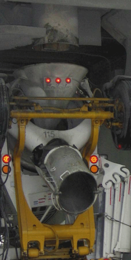
If the truck loadout is controlled by a baghouse then the DNR recommends the truck loadout be modeled as a point source using the stack characteristics of the baghouse. However, if it is not controlled by a baghouse, then the DNR recommends the truck loadout be modeled as a volume source. The DNR recommends the release height be based on the height of the loadout spout and opening in the truck. The σy is the square-root of the surface area of the opening in the back of the mixer truck divided by 4.3. The σz is the square-root of the surface area of the opening in the back of the mixer truck divided by 2.15. It can be assumed that the opening of the back of the truck is approximately four feet in diameter. Therefore, the σy and σz of the truck loadout volume source are 0.82 and 1.65 feet respectively. This represents emissions as they are generated by filling the back of the truck as well as the emissions that escape out of the truck after entering.
This source can be assumed to operate for 42.5 minutes out of each hour. Therefore the modeled hourly emission rate can be reduced by a factor of 42.5/60.
Central Mixer Loading
This source is only applicable at central mix facilities. Emissions are generated as the cement, supplement, sand and aggregate are transferred to the central mixer. Emissions from the central mixer are sometimes controlled by a baghouse.
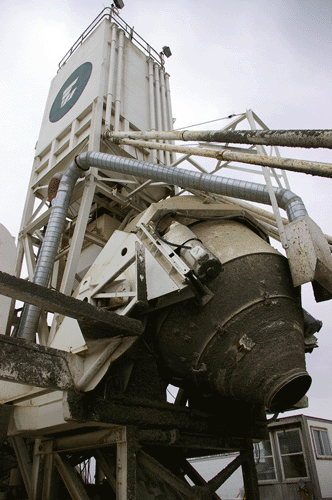
If the central mixer is controlled by a baghouse then the DNR recommends the central mixer be modeled as a point source using the stack characteristics of the baghouse. However, if it is not controlled by a baghouse, then the DNR recommends the central mixer be modeled as a volume source. The DNR recommends the release height be the height of the center of the mixer loading point. The σy is the square-root of the lateral area of the mixer divided by 4.3. The σz is the square-root of the height of the mixer divided by 2.15. If the dimensions of the mixer are unavailable, it can be assumed to be 11.5 long, 9 feet wide and 9 feet tall.
This source can be assumed to operate for 30 minutes out of each hour. Therefore the modeled hourly emission rate can be reduced by a factor of 30/60.
Boiler
Concrete batch plants use a boiler to heat the water that is added to the concrete during the colder months of the year. The DNR recommends the boiler be modeled as a point source using the characteristics of the boiler stack.
Generator
Occasionally, concrete batch plants will utilize a generator to provide electricity to run the conveyors and other equipment at the facility. The DNR recommends the generator be modeled as a point source using the characteristics of the generator stack.
Internal Emissions
The DNR recommends that any emission sources that are enclosed and vented inside of a building be modeled as a volume source, or series of volume sources whose parameters are based on the dimensions of the building in which they are enclosed. A building enclosure credit may also be applied.
Read More :
Concrete Baching Plant over View
Concrete Baching Plant Modelling guied
How dose the concrete batching plant work?
What is the best type of concrete batch mixer
Installation Tips of Batching Plant